
3MF Beam Lattice: Read the Geometry Before Strength Claims
2026-11-04
3MF Beam Lattice: Read the Geometry Before Strength Claims
A 3MF Beam Lattice description represents geometric relationships. Its presence in a manufacturing file does not report how a printed lattice performed under load. The currently published extension and Core specification provide a useful reading path: identify the mesh context, understand how beam endpoints refer to vertices and preserve the distinction between represented geometry and a manufactured result.
The extension belongs with the Core specification
The official Beam Lattice extension specification is an addendum to the 3MF Core format. The published text examined here identifies version 1.2.0 and states its Core 1.x context. An extension document should therefore be read with the corresponding core concepts, rather than treated as a standalone manufacturing language.
For a technical article, name the document context instead of saying only that a file is 3MF. The package may use particular extensions, and a reader needs to know which part of the representation is being discussed. A general format label cannot explain every specialized structure within it.
This article reads the specification without opening a supplied manufacturing job or checking a slicer's support. A published extension is evidence that a representation is specified. It does not establish that any particular application has implemented all of its features.
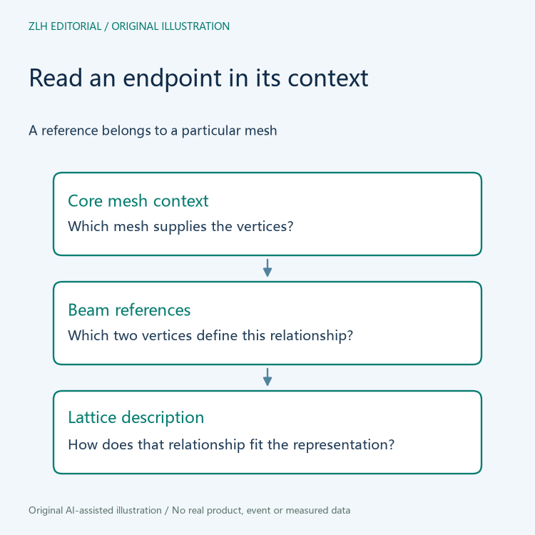
Beam endpoints refer to the mesh's vertex list
The extension describes beam endpoint references through its v1 and v2 fields, which identify vertices in the associated mesh. This relationship is more specific than drawing two dots and a line in an illustration. The references have meaning within the mesh data to which they belong.
Suppose two separate mesh resources each contain an endpoint reference with the same written index. That coincidence alone does not show that the points occupy the same location or identify the same geometric element. The mesh context must travel with the reference when the description is summarized.
This hypothetical reading example contains no actual coordinates or lattice counts. It explains why a detached endpoint table can lose information even when its numbers are transcribed accurately. The missing relationship cannot be repaired by choosing a visually plausible point in a preview.
Coordinate context is part of the geometry description
The official 3MF Core specification provides the surrounding coordinate-space and mesh concepts. The extension places its beam-lattice element within a mesh and relates it to that mesh's coordinate context. These references help explain where the lattice is represented, without supplying a physical test result.
A diagram exported from a viewer can illustrate that context, but the diagram's screen size is not a manufacturing dimension. If a technical discussion needs dimensions, it should use the relevant model information and units. It should not estimate them from how large an image appears on a webpage.
The same discipline applies when geometry is transformed for display. An editor should identify whether an illustration is explaining relationships or presenting actual model values. A conceptual picture can be useful while remaining deliberately free of coordinates, radii and any claim of an optimized structure.
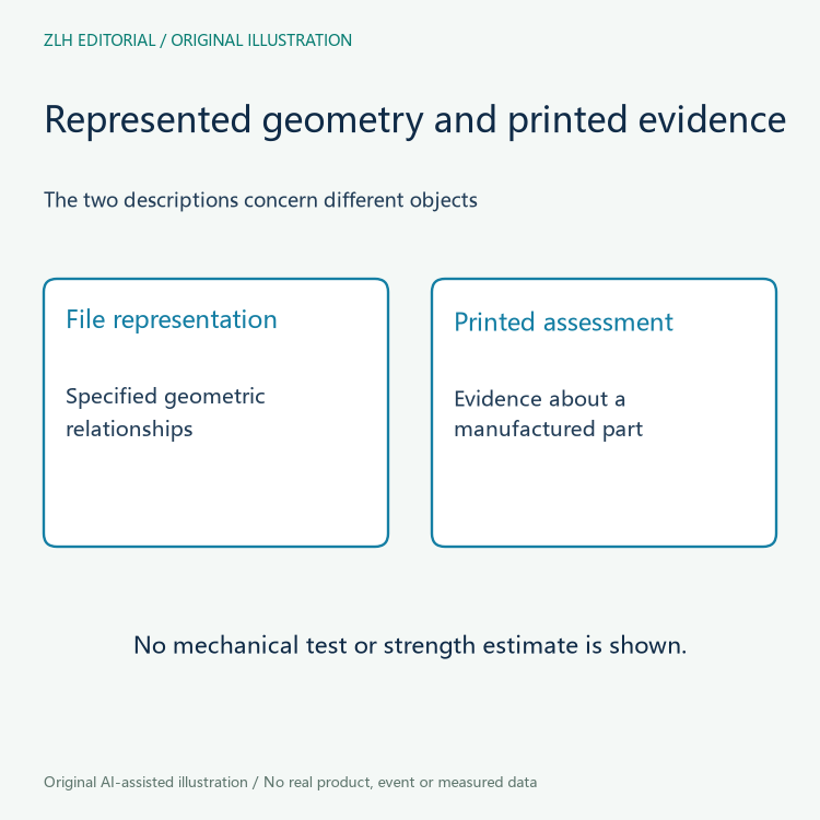
Printed strength requires evidence about the printed object
A geometric representation can describe connections, but it does not supply the material state and manufacturing history of an actual printed part. A claim about strength or durability would require evidence about the object and the conditions of that assessment. The existence of beams in a file is not that evidence.
For this reason, a source-based format explanation should avoid turning geometric detail into a universal performance promise. It should not infer that a denser-looking drawing is stronger, that a particular radius is appropriate for a machine or that a preview has established printability.
No mechanical analysis, fabrication trial or inspection was performed for this article. The original illustrations are relationship diagrams, not meshes to manufacture or images of a qualified component. They contain no settings that could be copied into a production job.
Use the file terms to improve the question being asked
A precise reading can state which extension is involved, which mesh supplies the endpoint references and which coordinate context makes those references meaningful. That gives a recipient a clearer basis for asking whether the intended software can interpret the supplied representation.
It also leaves performance questions with the evidence that can actually answer them. Format interpretation and manufactured-part assessment can inform each other without becoming the same activity. Where a report contains only a representation, preserve that limit in both the title and the image captions.
Further material appears in the 3D printing format interpretation collection and the article directory. Reading beam geometry carefully makes a lattice description more understandable while keeping unsupported strength claims out of the account.